HOW TO SWAPPING OUT SPARK PLUGS.

Swapping Out Spark Plugs: An Overview
Changing spark plugs isn't too hard, even for the mechanically disinclined. If you're careful, you should have little trouble.
How do you know if your plugs need to be changed? The surest sign is on your odometer. Spark plugs usually need to be changed every 30,000 miles (48,280 kilometers). Some high-performance plugs can go as long as 100,000 miles (160,934 km) before replacement. If you don't know when yours were last changed or if you have an engine that runs roughly or has recently exhibited a decrease in fuel economy, well, that could mean that your engine might benefit from some fresh, clean sparks. As always, check the owner's manual to see what works best for your vehicle.

SPARK PLUG PARTS; THE TOP TO BOTTOM TOUR.

Spark Plug Parts: The Top-to-Bottom Tour
At the top of the spark plug sits the connector, or terminal. This is where the spark plug wire attaches. The terminal connects inside the plug to the copper core of the center electrode, which is surrounded by insulation.

SPARK PLUG BASICS

Spark Plug Basics
It seems pretty obvious that a spark plug provides the spark that burns the fuel, but its secondary role as a heat dissipater is equally important. A spark plug's ability to transfer heat to the cars cooling system is based on the length of the insulator nose and the materials used for the center electrode and the insulator.

HOW SPARK PLUGS WORK.

How Spark Plugs Work


Spark plugs are one of the few things that an amateur mechanic can repair without much trouble

As Engine and their electronics become more complex, one of the few things left to hobbyists and auto enthusiasts who like a little grease under their fingernails is the ability to change their spark plugs. Although just about every other car repair out there takes a code reader and a college degree to diagnose and fix, spark plugs remain accessible and easy to understand.

WATER PUMP ( CENTRIFUGAL TYPE )

Water Pump
                                    A centrifugal pump like the one used in your car.

HOW DOES THE THERMOSTAT WORKS IN CAR.

How does the thermostat in a car's cooling system work?
Any liquid-cooled car engine has a small device called the thermostat that sits between the engine and the radiator. The thermostat in most cars is about 2 inches (5 cm) in diameter. Its job is to block the flow of coolant to the radiator until the engine has warmed up. When the engine is cold, no coolant flows through the engine. Once the engine reaches its operating temperature (generally about 200 degrees F, 95 degrees C), the thermostat opens. By letting the engine warm up as quickly as possible, the thermostat reduces engine wear, deposits and emissions.

SUPERCHARGER ADVANTAGES

Supercharger Advantages
The biggest advantage of having a supercharger is the increased horsepower. Attach a supercharger to an otherwise normal Car or Truck, and it will behave like a vehicle with a larger, more powerful engine.
But what if someone is trying to decide between a supercharger and a turbocharger? This question is hotly debated by auto engineers and car enthusiasts, but in general, superchargers offer a few advantages over turbochargers.
Superchargers do not suffer lag -- a term used to describe how much time passes between the driver depressing the gas pedal and the engine's response. Turbochargers suffer from lag because it takes a few moments before the exhaust gases reach a velocity that is sufficient to drive the impeller/turbine. Superchargers have no lag time because they are driven directly by the crankshaft. Certain superchargers are more efficient at lower RPM, while others are more efficient at higher RPM. Roots and twin-screw superchargers, for example, provide more power at lower RPM. Centrifugal superchargers, which become more efficient as the impeller spins faster, provide more power at higher RPM.

Installing a turbocharger requires extensive modification of the exhaust system, but superchargers can be bolted to the top or side of the engine. That makes them cheaper to install and easier to service and maintain.

CENTRIFUGAL SUPERCHARGERS

Centrifugal Superchargers

ProCharger D1SC centrifugal supercharger
A centrifugal supercharger powers an impeller -- a device similar to a rotor -- at very high speeds to quickly draw air into a small compressor housing. Impeller speeds can reach 50,000 to 60,000 RPM. As the air is drawn in at the hub of the impeller, centrifugal force causes it to radiate outward. The air leaves the impeller at high speed, but low pressure. A diffuser -- a set of stationary vanes that surround the impeller -- converts the high-speed, low-pressure air to low-speed, high-pressure air. Air molecules slow down when they hit the vanes, which reduces the velocity of the airflow and increases pressure.

TWIN SCREW SUPERCHARGERS

Twin-screw Superchargers


Twin-screw supercharger
A twin-screw supercharger operates by pulling air through a pair of meshing lobes that resemble a set of worm gears. Like the Roots supercharger, the air inside a twin-screw supercharger is trapped in pockets created by the rotor lobes. But a twin-screw supercharger compresses the air inside the rotor housing. That's because the rotors have a conical taper, which means the air pockets decrease in size as air moves from the fill side to the discharge side. As the air pockets shrink, the air is squeezed into a smaller space.

ROOTS SUPERCHARGERS

Roots Superchargers

The Eaton supercharger, a modified Roots supercharger.
There are three types of superchargers: Roots, twin-screw and centrifugal. The main difference is how they move air to the intake manifold of the engine. Roots and twin-screw superchargers use different types of meshing lobes, and a centrifugal supercharger uses an impeller, which draws air in. Although all of these designs provide a boost, they differ considerably in their efficiency. Each type of supercharger is available in different sizes, depending on whether you just want to give your car a boost or compete in a race.

The Roots supercharger is the oldest design. Philander and Francis Roots patented the design in 1860 as a machine that would help ventilate mine shafts. In 1900, Gottleib Daimler included a Roots supercharger in a car engine.

BASIC SUPERCHARGER

A basic engine with the addition of a supercharger.
An ordinary four-stroke engine dedicates one stroke to the process of air intake. There are three steps in this process:
11.     The piston moves down.
22.     This creates a vacuum.
33.     Air at atmospheric pressure is sucked into the combustion chamber.
Once air is drawn into the engine, it must be combined with fuel to form the charge -- a packet of potential energy that can be turned into useful kinetic energy through a chemical reaction known as combustion. The spark plug initiates this chemical reaction by igniting the charge. As the fuel undergoes oxidation, a great deal of energy is released. The force of this explosion, concentrated above the cylinder head, drives the piston down and creates a reciprocating motion that is eventually transferred to the wheels.

HOW SUPERCHARGERS WORK.

How Superchargers Work

Since the invention of the internal combustion engine, automotive engineers, speed junkies and race car designers have been searching for ways to boost its power. ­One way to add power is to build a bigger engine. But bigger engines, which weigh more and cost more to build and maintain, are not always better.

.

USING TWO TURBOCHARGERS

Using Two Turbochargers & More Turbo Parts
Some engines use two turbochargers of different sizes. The smaller one spins up to speed very quickly, reducing lag, while the bigger one takes over at higher engine speeds to provide more boost.
When air is compressed, it heats up; and when air heats up, it expands. So some of the pressure increase from a turbocharger is the result of heating the air before it goes into the engine. In order to increase the power of the engine, the goal is to get more air molecules into the cylinder, not necessarily more air pressure.

TURBOCHARGER PARTS

Turbocharger Parts
One of the main problems with turbochargers is that they do not provide an immediate power boost when you step on the gas. It takes a second for the turbine to get up to speed before boost is produced. This results in a feeling of lag when you step on the gas, and then the car lunges ahead when the turbo gets moving.
Turbochargers provide boost to engines at high speeds

TURBOCHARGER DESIGN

Turbocharger Design

The turbocharger is bolted to the exhaust manifold of the engine. The exhaust from the cylinders spins the turbine, which works like a gas turbine engine. The turbine is connected by a shaft to the compressor, which is located between the air filter and the intake manifold. The compressor pressurizes the air going into the pistons.
How a turbocharger is plumbed in a car

TURBOCHARGERS AND ENGINES

Turbochargers and Engines
One of the surest ways to get more power out of an engine is to increase the amount of air and fuel that it can burn. One way to do this is to add cylinders or make the current cylinders bigger. Sometimes these changes may not be feasible -- a turbo can be a simpler, more compact way to add power, especially for an aftermarket accessory.
Turbochargers allow an engine to burn more fuel and air by packing more into the existing cylinders. The typical boost provided by a turbocharger is 6 to 8 pounds per square inch (psi). Since normal atmospheric pressure is 14.7 psi at sea level, you can see that you are getting about 50 percent more air into the engine. Therefore, you would expect to get 50 percent more power. It's not perfectly efficient, so you might get a 30- to 40-percent improvement instead.
One cause of the inefficiency comes from the fact that the power to spin the turbine is not free. Having a turbine in the exhaust flow increases the restriction in the exhaust. This means that on the exhaust stroke, the engine has to push against a higher back-pressure. This subtracts a little bit of power from the cylinders that are firing at the same time.­


HOW TURBOCHARGERS WORK

How Turbochargers Work

When people talk about cars or high-performance sports cars, the topic of turbochargers usually comes up. Turbochargers also appear on large diesel engines. A turbo can significantly boost an engine's horsepower without significantly increasing its weight, which is the huge benefit that makes turbos so popular!
In this article, we'll learn how a turbocharger increases the power output of an engine while surviving extreme operating conditions. We'll also learn how waste gates, ceramic turbine blades and ball bearing help turbochargers do their job even better. Turbochargers are a type of forced induction system. They compress the air flowing into the engine. The advantage of compressing the air is that it lets the engine squeeze more air into a cylinder, and more air means that more fuel can be added. Therefore, you get more power from each explosion in each cylinder. A turbocharged engine produces more power overall than the same engine without the charging. This can significantly improve the power-to-weight ratio for the engine

In order to achieve this boost, the turbocharger uses the exhaust flow from the engine to spin a turbine, which in turn spins an air pump. The turbine in the turbocharger spins at speeds of up to 150,000 rotations per minute (rpm) -- that's about 30 times faster than most car engines can go. And since it is hooked up to the exhaust, the temperatures in the turbine are also very high.

THE FUTURE OF POWER STEERING

The Future of Power Steering
Since the power-steering pump on most cars today runs constantly, pumping fluid all the time, it wastes horsepower. This wasted power translates into wasted fuel.
You can expect to see several innovations that will improve fuel economy. One of the coolest ideas on the drawing board is the "steer-by-wire" or "drive-by-wire" system. These systems would completely eliminate the mechanical connection between the steering wheel and the steering, replacing it with a purely electronic control system. Essentially, the steering wheel would work like the one you can buy for your home computer to play games. It would contain sensors that tell the car what the driver is doing with the wheel, and have some motors in it to provide the driver with feedback on what the car is doing. The output of these sensors would be used to control a motorized steering system. This would free up space in the engine compartment by eliminating the steering shaft. It would also reduce vibration inside the car.
General Motors has introduced a concept car, the Hy-wire that features this type of driving system. One of the most exciting things about the drive-by-wire system in the GM Hy-wire is that you can fine-tune vehicle handling without changing anything in the car's mechanical components -- all it takes to adjust the steering is some new computer software. In future drive-by-wire vehicles, you will most likely be able to configure the controls exactly to your liking by pressing a few buttons, just like you might adjust the seat position in a car today. It would also be possible in this sort of system to store distinct control preferences for each driver in the family.
In the past fifty years, car steering systems haven't changed much. But in the next decade, we'll see advances in car steering that will result in more efficient cars and a more comfortable ride.


POWER STEERING.


Power Steering
There are a couple of key components in power steering in addition to the rack-and-pinion or recirculating-ball mechanism.

RECIRCULATING BALL STEERING


Recirculating-ball Steering
Recirculating-ball steering is used on many trucks and SUVs today. The linkage that turns the wheels is slightly different than on a rack-and-pinion system.

STEERING RACK AND PINION


Rack-and-pinion Steering
Rack-and-pinion steering is quickly becoming the most common type of steering on cars, small trucks and SUVs. It is actually a pretty simple mechanism. A rack-and-pinion gear set is enclosed in a metal tube, with each end of the rack protruding from the tube. A rod, called a tie rod, connects to each end of the rack.
The pinion gear is attached to the steering shaft. When you turn the steering wheel, the gear spins, moving the rack. The tie rod at each end of the rack connects to the steering arm on the spindle (see diagram above).
The rack-and-pinion gear set does two things:
·         It converts the rotational motion of the steering wheel into the linear motion needed to turn the wheels.
·         It provides a gear reduction, making it easier to turn the wheels.
On most cars, it takes three to four complete revolutions of the steering wheel to make the wheels turn from lock to lock (from far left to far right).

HOW CAR STEERING WORKS

How Car Steering Works

You know that when you turn the steering wheel in your car, the wheels turn. Cause and effect, right? But a lot of interesting stuff goes on between the steering wheel and the tires to make this happen.
In this article, we'll see how the two most common types of c­ar steering systems work: rack-and-pinion and recirculating-ball steering. Then we'll examine power steering and find out about some interesting future developments in steering systems, driven mostly by the need to increase the fuel efficiency of cars. But first, let's see what you have to do turn a car. It's not quite as simple as you might think!

Turning the Car

You might be surprised to learn that when you turn your car, your front wheels are not pointing in the same direction.
For a car to turn smoothly, each wheel must follow a different circle. Since the inside wheel is following a circle with a smaller radius, it is actually making a tighter turn than the outside wheel. If you draw a line perpendicular to each wheel, the lines will intersect at the center point of the turn. The geometry of the steering linkage makes the inside wheel turn more than the outside wheel.

FOUR WHEEL DRIVE DIFFERENTIAL

Four-wheel Drive Differential
The type of part-time system typically found on four-wheel-drive pickups and older SUVs works like this: The vehicle is usually rear-wheel drive. The transmission hooks up directly to a transfer case. From there, one drive shaft turns the front axle, and another turns the rear axle.
When four-wheel drive is engaged, the transfer case locks the front drive shaft to the rear drive shaft, so each axle receives half of the torque coming from the engine. At the same time, the front hubs lock.

COMPONENTS OF A FOUR WHEEL DRIVE SYSTEM.

Components of a Four-wheel-drive System


The main parts of any four-wheel-drive system are the two differentials (front and rear) and the transfer case. In addition, part-time systems have locking hubs, and both types of systems may have advanced electronics that help them make even better use of the available traction.

TORQUE, TRACTION AND WHEEL SLIP

Torque, Traction and Wheel Slip
Torque is the twisting force that the engine produces. The torque from the engine is what moves your car. The various gears in the transmission and differential multiply the torque and split it up between the wheels. More torque can be sent to the wheels in first gear than in fifth gear because first gear has a larger gear-ratio by which to multiply the torque.
The bar graph below indicates the amount of torque that the engine is producing. The mark on the graph indicates the amount of torque that will cause wheel slip. The car that makes a good start never exceeds this torque, so the tires don't slip; the car that makes a bad start exceeds this torque, so the tires slip. As soon as they start to slip, the torque drops down to almost zero.
The interesting thing about torque is that in low-traction situations, the maximum amount of torque that can be created is determined by the amount of traction, not by the engine. Even if you have a NASCAR engine in your car, if the tires won't stick to the ground there is simply no way to harness that power.
For the sake of this article, we'll define traction as the maximum amount of force the tire can apply against the ground (or that the ground can apply against the tire -- they're the same thing). These are the factors that affect traction:
The weight on the tire -- The more weight on a tire, the more traction it has. Weight can shift as a car drives. For instance, when a car makes a turn, weight shifts to the outside wheels. When it accelerates, weight shifts to the rear wheels. 
The coefficient of friction -- This factor relates the amount of friction force between two surfaces to the force holding the two surfaces together. In our case, it relates the amount of traction between the tires and the road to the weight resting on each tire. The coefficient of friction is mostly a function of the kind of tires on the vehicle and the type of surface the vehicle is driving on. For instance, a NASCAR tire has a very high coefficient of friction when it is driving on a dry, concrete track. That is one of the reasons why NASCAR race cars can corner at such high speeds. The coefficient of friction for that same tire in mud would be almost zero. By contrast, huge, knobby, off-road tires wouldn't have as high a coefficient of friction on a dry track, but in the mud, their coefficient of friction is extremely high.

HOW FOUR WHEEL DRIVE WORKS.

How Four-Wheel Drive Works
There are almost as many different types of four-wheel-drive systems as there are four-wheel-drive vehicles. It seems that every manufacturer has several different schemes for providing power to all of the wheels. The language used by the different car makers can sometimes be a little confusing, so before we get started explaining how they work, let's clear up some terminology:
·       

LOCKING AND TOR SEN

Locking and Tor sen
The locking differential is useful for serious off-road vehicles. This type of differential has the same parts as an open differential, but adds an electric, pneumatic or hydraulic mechanism to lock the two output pinions together.
This mechanism is usually activated manually by switch, and when activated, both wheels will spin at the same speed. If one wheel ends up off the ground, the other wheel won't know or care. Both wheels will continue to spin at the same speed as if nothing had changed.
The Tor sen differential* is a purely mechanical device; it has no electronics, clutches or viscous fluids.
The Tor sen (from Torque Sensing) works as an open differential when the amount of torque going to each wheel is equal. As soon as one wheel starts to lose traction, the difference in torque causes the gears in the Tor sen differential to bind together. The design of the gears in the differential determines the torque bias ratio. For instance, if a particular Tor sen differential is designed with a 5:1 bias ratio, it is capable of applying up to five times more torque to the wheel that has good traction.
These devices are often used in high-performance all-wheel-drive vehicles. Like the viscous coupling, they are often used to transfer power between the front and rear wheels. In this application, the Tor sen is superior to the viscous coupling because it transfers torque to the stable wheels before the actual slipping occurs.
However, if one set of wheels loses traction completely, the Tor sen differential will be unable to supply any torque to the other set of wheels. The bias ratio determines how much torque can be transferred, and five times zero is zero.


VISCOUS COUPLING

Viscous Coupling
The viscous coupling has two sets of plates inside a sealed housing that is filled with a thick fluid, as shown in below. One set of plates is connected to each output shaft. Under normal conditions, both sets of plates and the viscous fluid spin at the same speed. When one set of wheels tries to spin faster, perhaps because it is slipping, the set of plates corresponding to those wheels spins faster than the other. The viscous fluid, stuck between the plates, tries to catch up with the faster disks, dragging the slower disks along. This transfers more torque to the slower moving wheels -- the wheels that are not slipping.

FINAL DRIVE CLUTCH-TYPE LIMITED SLIP DIFFERENTIAL

Clutch-type Limited Slip Differential
The clutch-type LSD is probably the most common version of the limited slip differential
This type of LSD has all of the same components as an open differential, but it adds a spring pack and a set of clutches. Some of these have a cone clutch that is just like the synchronizers in a manual Transmission

DIFFERENTIAL AND TRACTION

Differentials and Traction
The open differential always applies the same amount of torque to each wheel. There are two factors that determine how much torque can be applied to the wheels: equipment and traction. In dry conditions, when there is plenty of traction, the amount of torque applied to the wheels is limited by the engine and gearing; in a low traction situation, such as when driving on ice, the amount of torque is limited to the greatest amount that will not cause a wheel to slip under those conditions. So, even though a car may be able to produce more torque, there needs to be enough traction to transmit that torque to the ground. If you give the car more gas after the wheels start to slip, the wheels will just spin faster.

FUNGUA DIFFERENTIAL ( OPEN DIFFERENTIAL )

Open Differentials
We will start with the simplest type of differential, called an open differential. First we'll need to explore some terminology: The image below labels the components of an open differential.

When a car is driving straight down the road, both drive wheels are spinning at the same speed. The input pinion is turning the ring gear and cage, and none of the pinions within the cage are rotating -- both side gears are effectively locked to the cage.


Note that the input pinion is a smaller gear than the ring gear; this is the last gear reduction in the car. You may have heard terms like rear axle ratio or final drive ratio. These refer to the gear ratio in the differential. If the final drive ratio is 4.10, then the ring gear has 4.10 times as many teeth as the input pinion gear. 


DIFFERENTIAL NI NINI? ( WHAT IS A DIFFERENTIAL? )

What is a Differential?

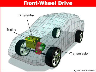
The differential is a device that splits the engine torque two ways, allowing each output to spin at a different speed.
The differential is found on all modern cars and trucks, and also in many all-wheel-drive (full-time four-wheel-drive) vehicles. These all-wheel-drive vehicles need a differential between each set of drive wheels, and they need one between the front and the back wheels as well, because the front wheels travel a different distance through a turn than the rear wheels.
Part-time four-wheel-drive systems don't have a differential between the front and rear wheels; instead, they are locked together so that the front and rear wheels have to turn at the same average speed. This is why these vehicles are hard to turn on concrete when the four-wheel-drive system is engaged.


JINSI DIFFERENTIAL INAVYOFANYA KAZI (HOW DIFFERENTIALS WORKS )

How Differentials Work

                Differential-ch

If you've read How Car Engine Works, you understand how a car's power is generated; and if you've read How Manual Transmission Works, you understand where the power goes next. This article will explain differentials -- where the power, in most cars, makes its last stop before spinning the wheels.

AINA ZA KRACHI ( TYPES OF CLUTCHES )

Types of Clutches
There are many other types of clutches in your car and in your garage.
An automatic transmission contains several clutches. These clutches engage and disengage various sets of planetary gears. Each clutch is put into motion using pressurized hydraulic fluid. When the pressure drops, springs cause the clutch to release. Evenly spaced ridges, called splines, line the inside and outside of the clutch to lock into the gears and the clutch housing. You can read more about these clutches in How Automatic Transmission Works.

TUANGALIE KWA KAWAIDA MATATIZO YA CLUTCH.( COMMON PROBLEMS

Common Problems
From the 1950s to the 1970s, you could count on getting between 50,000 and 70,000 miles from your car clutch. Clutches car's can now last for more than 80,000 miles if you use them gently and maintain them well. If not cared for, clutches can start to break down at 35,000 miles. Trucks that are consistently overloaded or that frequently tow heavy loads can also have problems with relatively new clutches.

FLY WHEELS, CLUTCH PLATES AND FRICTION ( MSUGUANO )

Fly Wheels, Clutch Plates and Friction
In a Car's clutch, a flywheel connects to the engine, and a clutch plate connects to the transmission. You can see what this looks like in the video clip below.

TUANGALIE UFANYAJI KAZI WA KRATCHI ( HOW CLUTCHES WORKS )

How Clutches Work
        Diagram of car showing clutch location

If you drive a manual transmission car, you may be surprised to find out that it has more than one clutch. And it turns out that folks with automatic cars have clutches, too. In fact, there are clutches in many things you probably see or use every day: Many cordless drills have a clutch, chain saw have a centrifugal clutch and even some  have a clutch.

TUANGALIE PLANETARY GEAR SET

The Planetary Gear set
     From left to right: the ring gear, planet carrier, and two sun gears
When you take apart and look inside an automatic transmission, you find a huge assortment of parts in a fairly small space. Among other things, you see:
·         An ingenious planetary gear set
·         A set of bands to lock parts of a gear set
·         A set of three wet-plate clutches to lock other parts of the gear set
·         An incredibly odd hydraulic system that controls the clutches and bands
·         A large gear pump to move transmission fluid around
The center of attention is the planetary gear set. About the size of a cantaloupe, this one part creates all of the different gear ratios that the transmission can produce. Everything else in the transmission is there to help the planetary gear set do its thing. An automatic transmission contains two complete planetary gear sets folded together into one component. See How gear ratio works for an introduction to planetary gear sets.
Any planetary gear set has three main components:
·         The sun gear
·         The planet gears and the planet gears' carrier
·         The ring gear
Each of these three components can be the input, the output or can be held stationary. Choosing which piece plays which role determines the gear ratio for the gear set.
Planetary Gear set Ratios
One of the planetary gear sets from our transmission has a ring gear with 72 teeth and a sun gear with 30 teeth. We can get lots of different gear ratios out of this gear set.
Input
Output
Stationary
Calculation
Gear Ratio
A
Sun (S)
Planet Carrier (C)
Ring (R)
1 + R/S
3.4:1
B
Planet Carrier (C)
Ring (R)
Sun (S)
1 / (1 + S/R)
0.71:1
C
Sun (S)
Ring (R)
Planet Carrier (C)
-R/S
-2.4:1

Also, locking any two of the three components together will lock up the whole device at a 1:1 gear reduction. Notice that the first gear ratio listed above is a reduction -- the output speed is slower than the input speed. The second is an overdrive -- the output speed is faster than the input speed. The last is a reduction again, but the output direction is reversed. There are several other ratios that can be gotten out of this planetary gear set, but these are the ones that are relevant to our automatic transmission. You can try these out in the animation below:
Animation of the different gear ratios related to automatic transmissions.


So this one set of gears can produce all of these different gear ratios without having to engage or disengage any other gears. With two of these gear sets in a row, we can get the four forward gears and one reverse gear our transmission needs.